

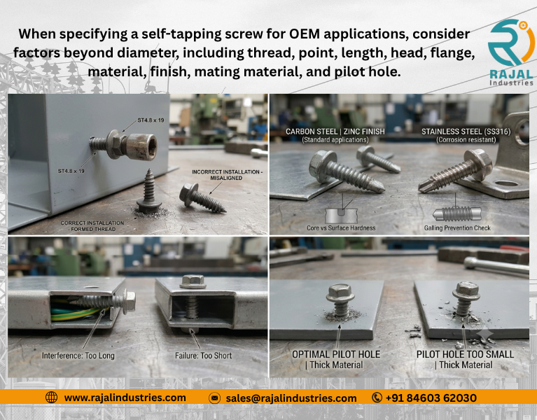
A Hex Flange Self Tapping Screw combines an external hex drive, an integrated flange and a self-tapping thread in one fastener.
For engineers and buyers, selecting the correct screw requires more than knowing its nominal diameter and length.
A complete specification may need:
Diameter + Thread Form + Length + Hex Head + Flange + Point + Material + Mechanical Properties + Finish + Mating Material + Pilot Hole
These details are particularly important for automotive, sheet-metal and industrial OEM applications because the screw must create or develop a suitable mating thread during installation.
This guide explains how to specify Hex Flange Self Tapping Screw sizes, dimensions, materials, threads, points and other technical requirements without relying on incomplete catalogue descriptions.
Quick Answer: How Is a Hex Flange Self-Tapping Screw Specified?
A Hex Flange Self Tapping Screw should normally be specified by its nominal screw size, thread form, length, head and flange geometry, point design, material, mechanical properties and surface finish.
For OEM applications, also define the:
- Mating material
- Material thickness
- Pilot-hole diameter
- Installation requirements
- Testing requirements
The approved drawing or applicable product standard should remain the primary technical reference.
What Is a Hex Flange Self-Tapping Screw?
A hex flange self-tapping screw has three main characteristics:
1. External Hex Drive
The screw can be installed using an appropriate:
- Socket
- Nut setter
- Wrench
- Powered installation tool
2. Integrated Flange
The flange provides a wider under-head bearing surface than some conventional hex-head designs.
3. Self-Tapping Thread
The screw is designed to form or cut a mating thread in a suitable material and hole condition.
The exact performance depends on the specific screw design.
Basic Hex Flange Self-Tapping Screw Anatomy
A typical screw can be divided into:
Hex Head → Integrated Flange → Shank/Thread → Tapping Section → Point
Important dimensions can include:
| Feature | What It Defines |
| Nominal Diameter | Basic screw size |
| Thread Geometry | Mating-thread formation |
| Length | Required engagement |
| Across Flats | Hex tool size |
| Head Height | Head profile |
| Flange Diameter | Bearing area |
| Flange Thickness | Flange geometry |
| Thread Length | Available engagement |
| Point Geometry | Starting/tapping behaviour |
Not every product family uses exactly the same dimensional definitions.
Always follow the relevant standard or approved drawing.
Hex Flange Self-Tapping Screw Size Designation
A screw description should give enough information for the manufacturer to identify the actual requirement.
A simplified example could be:
ST4.8 × 19 – Hex Flange – Specified Point – Carbon Steel – Specified Finish
This is an illustration only.
The exact thread designation, point, head geometry, material and finish should follow the applicable specification.
For custom industrial fasteners, a drawing is preferable to relying on a short product description.
What Does the Nominal Screw Size Mean?
The nominal size identifies the basic screw/thread diameter according to the applicable screw system.
However, nominal diameter alone does not define:
- Exact thread profile
- Pitch
- Point
- Head dimensions
- Flange dimensions
- Length
- Material
- Finish
For example:
“4.8 mm self-tapping screw”
is not a complete OEM specification.
Common Self-Tapping Size Ranges
Self-tapping screws are manufactured in many diameters and lengths.
Commercial requirements may include relatively small screws for:
- Electronics
- Appliances
- Light sheet metal
and larger screws for:
- Automotive components
- Industrial equipment
- Fabricated assemblies
- HVAC equipment
Instead of publishing a universal size chart, buyers should use the exact applicable standard or manufacturer-approved dimensional data.
This avoids mixing dimensions from different self-tapping screw families.
Why We Should Not Use One Universal Size Chart
Two screws described as:
Hex Flange Self-Tapping Screws
may differ in:
- Thread form
- Pitch
- Point
- Hex size
- Head height
- Flange diameter
- Material
- Mechanical properties
A dimension table is useful only when it is tied to a clearly identified standard or drawing.
For OEM sourcing, uncontrolled internet dimension charts can create purchasing errors.
What Are Self Tapping Sizes?
The keyword Self Tapping Sizes can refer to several different characteristics:
- Screw diameter
- Thread designation
- Length
- Thread length
- Point length
- Head size
- Flange diameter
Therefore, when a buyer asks:
“Which self-tapping sizes do you manufacture?”
the technical answer should clarify whether they mean:
Diameter, Length, Thread Type or Complete Screw Standard.
Screw Diameter Selection
The correct diameter depends on:
- Mating material
- Material thickness
- Pilot hole
- Required engagement
- Joint requirement
- Available space
A larger diameter is not automatically stronger or better for the application.
Changing screw diameter also changes the required:
- Hole
- Thread interaction
- Head geometry
- Installation behaviour
Screw Length Selection
Length should be selected according to:
Component Stack + Required Thread Engagement + Available Clearance
The screw should be long enough to develop the required joint without unnecessary excess length.
Why Screw Length Matters
A screw that is too short can cause:
- Insufficient engagement
- Incomplete thread development
- Poor retention
A screw that is too long can cause:
- Internal interference
- Contact with wiring
- Contact with moving parts
- Increased assembly time
- Product damage
The application should therefore determine the length.
How Is Hex Flange Self-Tapping Screw Length Measured?
Length measurement depends on the screw’s head style and applicable product specification.
For many non-countersunk head screws, nominal length is measured from the bearing surface under the head to the screw tip.
However, buyers should verify the measurement convention from the applicable standard or drawing.
Do not assume every screw family uses the same length convention.
Overall Length vs Nominal Length
These terms should not automatically be treated as identical.
Nominal Length
Usually follows the dimensional convention defined by the product standard.
Overall Length
May refer to the complete physical length, including head, depending on how a drawing or supplier defines it.
For custom drawings, clearly dimension the required reference points.
Hex Head Dimensions
The external hex head allows installation with a matching tool.
Important dimensions can include:
- Across flats
- Across corners
- Head height
- Edge geometry
- Head concentricity
For powered assembly, correct across-flats control helps maintain reliable socket or nut-setter engagement.
What Is “Across Flats”?
Across flats is the distance between two opposite parallel faces of the hexagonal head.
It determines the nominal fit of the installation tool.
If across flats is incorrect, possible problems include:
- Loose socket fit
- Tool slipping
- Head damage
- Assembly inconsistency
Across Corners
Across corners measures the maximum dimension across opposite corners of the hex.
This can matter where:
- Clearance is limited
- Head geometry is controlled
- Nearby features could interfere
It should not be confused with across flats.
Head Height
Head height affects:
- Overall product profile
- Tool engagement
- Available clearance
- Head strength
- Assembly packaging
For compact equipment, even a small head-height difference can create interference.
What Does the Flange Do?
The integrated flange creates a wider under-head bearing surface.
Depending on the joint, this can help:
- Distribute contact
- Support the material around the hole
- Provide controlled seating
- Reduce separate washer handling where approved
However, the flange does not automatically replace every washer.
Flange Diameter
Flange diameter is an important dimensional characteristic.
A larger flange can increase bearing area but can also create interference with:
- Nearby walls
- Formed features
- Adjacent screws
- Electrical components
- Assembly tooling
Therefore, flange diameter should follow the actual joint design.
Flange Thickness
Flange thickness can affect:
- Head geometry
- Bearing behaviour
- Clearance
- Manufacturing feasibility
For custom screws, flange thickness should be dimensioned clearly rather than left to interpretation.
Flange Flatness & Seating
The flange should seat as intended against the mating surface.
Potential problems include:
- Distorted flange
- Burrs
- Uneven bearing surface
- Component burrs
- Hole distortion
If a flange does not sit correctly, inspect both the screw and mating component.
Hex Washer Screws vs Hex Flange Screws
The term Hex Washer Screws is commonly used for screws with a wider washer-like bearing area under the hex head.
However, commercial terminology can vary.
A buyer should not assume:
Hex Washer Screw = One Universal Geometry
For OEM purchasing, specify:
Across Flats + Head Height + Bearing/Flange Diameter + Flange Thickness + Under-Head Geometry
Self-Tapping Thread Types
“Self-tapping” describes a broad functional category rather than one universal thread.
Different designs can:
- Form material
- Cut material
- Use different thread profiles
- Use different point geometries
The correct design depends on the mating material and application.
Thread-Forming Screws
Thread-forming screws primarily create the mating thread by displacing material.
Important variables include:
- Thread geometry
- Screw diameter
- Pilot hole
- Mating material
- Material hardness
- Material thickness
A suitable combination should be validated before production.
Thread-Cutting Screws
Thread-cutting screws use cutting features to remove some mating material while developing the internal thread.
Important variables can include:
- Cutting feature
- Point
- Hole size
- Mating material
- Chip generation
- Installation process
Thread-forming and thread-cutting designs should not be substituted without engineering review.
Self-Tapping vs Machine Screw Thread
A machine screw normally engages with a previously formed mating thread such as:
- Tapped hole
- Nut
- Threaded insert
A self-tapping screw is designed to develop its mating thread during installation in a suitable material/hole.
Therefore:
Machine Screw Thread ≠ Self-Tapping Thread
unless a particular engineered fastener system specifically defines otherwise.
Self-Tapping vs Self-Drilling
Another common specification error is confusing self-tapping and self-drilling screws.
Self-Tapping Screw
Primarily develops the mating thread.
Self-Drilling Screw
Uses a drill-point feature designed to create the hole and subsequently form the fastening thread within its rated application.
A self-tapping screw may still require a pre-punched or drilled hole.
Why Thread Pitch Matters
Thread pitch or equivalent spacing influences:
- Number of engaged threads
- Material displacement
- Installation behaviour
- Thread formation
- Retention
The thread specification should follow the screw design.
Do not substitute a different thread merely because nominal diameter is similar.
Thread Major Diameter
Major diameter is one of the important dimensions controlling screw thread geometry.
Variation can affect:
- Pilot-hole interaction
- Installation torque
- Thread formation
- Retention
Inspection requirements should follow the applicable screw standard or drawing.
Thread Root Geometry
The root region influences the overall thread form and screw cross-section.
For engineered self-tapping screws, thread geometry should be controlled as a system rather than inspecting only one diameter.
Thread Length
Thread length should provide sufficient engagement for the application.
Depending on the screw design, the entire nominal length may not provide fully developed thread because the point/tapping section can have different geometry.
This should be considered when checking usable engagement.
Point Geometry
The screw point helps:
- Locate the hole
- Start installation
- Guide the screw
- Begin the tapping process
Different self-tapping screw designs can use different point configurations.
The point should be specified by the applicable standard or drawing.
Why Point Geometry Matters
Incorrect point geometry can contribute to:
- Poor starting
- Misalignment
- High installation torque
- Hole damage
- Thread-formation problems
For automated assembly, consistent point geometry can be particularly important.
Point Length
Point length can affect:
- Total clearance
- Initial engagement
- Effective thread engagement
- Internal interference
This matters where space behind the component is limited.
Pilot Hole Specification
The pilot hole is one of the most important application dimensions for a Hex Flange Self Tapping Screw.
A complete application specification may define:
Hole Diameter + Tolerance + Hole Process + Burr Condition + Mating Material + Thickness
Without these details, functional performance can be difficult to predict.
Pilot Hole Too Small
A small pilot hole can increase material interference.
Possible results include:
- High tapping torque
- Thread damage
- Screw breakage
- Point damage
- Sheet distortion
Pilot Hole Too Large
An oversized pilot hole can reduce material engagement.
Possible results include:
- Low stripping resistance
- Poor retention
- Loose assembly
- Thread failure
Easy installation does not automatically mean the hole is correct.
Pilot Hole Size Is Not Universal
A pilot hole depends on:
- Screw diameter
- Thread form
- Point
- Material
- Hardness
- Thickness
- Required performance
Therefore, a universal pilot-hole chart should not be used blindly across different self-tapping screw designs.
Sheet Thickness
Material thickness affects how much material is available to develop the mating thread.
Thin Sheet
Potential concerns:
- Limited engagement
- Hole stripping
- Material distortion
Thicker Material
Potential concerns:
- Higher tapping resistance
- Increased installation torque
- Screw-property requirements
Both require application-specific evaluation.
Hole Manufacturing Method
The hole may be:
- Drilled
- Punched
- Laser cut
- Produced by another approved process
Different processes can produce different:
- Burrs
- Taper
- Edge conditions
- Diameter variation
For high-volume OEM applications, screw testing should ideally use production-representative holes.
Material Selection
The screw material should support:
- Self-tapping function
- Required mechanical properties
- Corrosion environment
- Manufacturing process
- Customer specification
Common categories can include:
Carbon Steel | Alloy Steel | Stainless Steel | Customer-Specified Material
Carbon Steel Hex Flange Self-Tapping Screws
Carbon steel can be suitable for many automotive, appliance, HVAC, electrical and general industrial applications.
Depending on the product specification, manufacturing may include controlled heat treatment and surface finishing.
Important requirements can include:
- Steel grade
- Mechanical properties
- Hardness
- Finish
- Corrosion performance
Alloy Steel Industrial Fasteners
Alloy steel may be specified where the application requires particular mechanical properties.
However, the material should not be selected simply because alloy steel sounds stronger.
The customer or applicable specification should define the required properties.
Stainless Steel Hex Flange Self-Tapping Screws
Stainless steel may be suitable where corrosion resistance is important.
Potential requirements can include:
- SS304 / A2-type
- SS316 / A4-type
- Other customer-specified grades
But stainless steel should not automatically replace a heat-treated carbon steel self-tapping screw.
The tapping function and mating material must also be considered.
SS304 vs SS316
| Factor | SS304 / A2-Type | SS316 / A4-Type |
| General Corrosion Resistance | Good | Generally improved in certain environments |
| Chloride Exposure | More limited | Generally better resistance |
| Cost | Usually lower | Usually higher |
| Indoor Industrial Use | Common | Application dependent |
| Coastal Applications | Needs evaluation | Often considered |
| Final Selection | Environment/specification | Environment/specification |
Neither material is universally “best.”
Stainless Steel & Galling
Stainless steel threaded assemblies can be susceptible to galling under certain combinations of:
- Material
- Surface condition
- Friction
- Speed
- Load
For self-tapping applications, the actual mating material and installation conditions should therefore be tested.
Material Specification vs Trade Name
Avoid incomplete descriptions such as:
“MS screw”
or:
“Stainless screw”
For OEM requirements, define the actual material specification or required properties.
This improves both quotation accuracy and quality control.
Mechanical Properties
Depending on the screw type and specification, relevant properties may include:
- Hardness
- Strength
- Toughness
- Torsional performance
- Surface/core properties
- Other application-specific requirements
Not every self-tapping screw uses the same property requirements.
Heat Treatment
Heat treatment can be important for certain self-tapping screw designs.
The process may be required to develop suitable:
- Surface properties
- Core properties
- Strength
- Toughness
- Tapping performance
The exact requirement should follow the material and product specification.
Surface Hardness vs Core Properties
For some hardened screw designs, both surface and core behaviour can matter.
The screw may need adequate thread/point performance while maintaining suitable toughness.
This is why specifying only:
“Hard screw required”
is technically incomplete.
Why Maximum Hardness Is Not Better
Excessive hardness can increase brittleness.
Insufficient hardness can reduce tapping performance.
The target should always be:
Specified & Validated Mechanical Properties
rather than maximum hardness.
Surface Finish Options
Depending on the application, possible finishes can include:
- Zinc-based coatings
- Black finishes
- Engineered corrosion-resistant coatings
- Passivation for suitable stainless fasteners
- Customer-specified finishes
The finish should be selected according to:
Corrosion + Friction + Appearance + Environment + OEM Specification
Zinc-Plated Self-Tapping Screws
Zinc-based finishes are commonly considered for suitable carbon-steel industrial fasteners.
But simply writing:
Zinc plated
may not fully define the requirement.
Where necessary, specify:
- Coating system
- Thickness
- Appearance
- Corrosion requirement
- Other customer-specific requirements
Black Self-Tapping Screws
“Black” describes appearance, not a complete corrosion specification.
Different black finishes can provide very different performance.
Buyers should specify the actual finish required.
Coating Thickness
Coating thickness can affect:
- Thread dimensions
- Tapping behaviour
- Friction
- Head geometry
- Tool fit
This becomes increasingly important as screw dimensions become smaller.
Coating & Installation Torque
A change in surface finish can change friction.
That can change:
- Tapping torque
- Seating behaviour
- Tightening response
For OEM validation, functional testing should preferably use the final production coating.
Corrosion Specification
Instead of requesting:
“Good rust protection”
define the applicable corrosion requirement or customer specification.
Where salt-spray or another corrosion test is required, specify the exact test standard, duration and acceptance criteria rather than relying on a generic coating name.
Dimensional Specification Checklist
A drawing for a custom Hex Flange Self Tapping Screw may need to control:
- Nominal diameter
- Thread geometry
- Thread pitch/spacing
- Thread length
- Screw length
- Point geometry
- Point length
- Across flats
- Across corners where required
- Head height
- Flange diameter
- Flange thickness
- Under-head geometry
- Material
- Mechanical properties
- Heat treatment
- Surface finish
- Coating requirements
- Dimensional tolerances
- Customer-specific marking
Application Specification Checklist
In addition to the screw drawing, provide:
- Mating material
- Material grade
- Material hardness where relevant
- Material thickness
- Pilot-hole diameter
- Hole tolerance
- Hole manufacturing process
- Installation method
- Required functional testing
- Production quantity
These details are especially important for self-tapping fasteners.
Inspection Requirements
Depending on the drawing and application, inspection may include:
| Characteristic | Possible Control |
| Diameter | Dimensional inspection |
| Thread | Applicable gauge / measurement |
| Length | Dimensional inspection |
| Hex Head | Across-flats check |
| Head Height | Dimensional inspection |
| Flange Diameter | Dimensional inspection |
| Flange Thickness | Dimensional inspection |
| Point | Profile / dimensional inspection |
| Material | Certificate / verification |
| Hardness | Testing where specified |
| Finish | Coating inspection |
| Appearance | Visual inspection |
| Function | Application installation test |
The inspection plan should be matched to the customer’s specification.
Functional Testing
Self-tapping fasteners benefit from application-based testing because dimensional inspection alone cannot fully confirm installation performance.
Potential functional tests can include:
Installation → Thread Formation → Seating → Retention / Strip Evaluation where specified
Use:
- Production screw
- Final coating
- Actual or representative mating material
- Correct material thickness
- Production-representative hole
This gives a more realistic result.
Tapping Torque
Tapping torque is the torque encountered while the screw creates or develops the mating thread.
It can be influenced by:
- Pilot-hole diameter
- Thread geometry
- Point
- Mating material
- Material hardness
- Thickness
- Screw properties
- Surface finish
There is no safe universal tapping-torque value based only on screw diameter.
Seating Torque
As the flange contacts the component, the installation moves toward the seating/tightening stage.
The required production setting depends on the complete joint.
Do not select installation torque from a generic screw-size chart alone.
Strip or Failure Condition
If installation continues beyond the appropriate range, potential failures can include:
- Mating thread stripping
- Screw breakage
- Head failure
- Material distortion
The acceptable installation process should therefore be established by engineering validation.
Complete Specification Example
Instead of:
Hex self-tapping screw, 4.8 × 19, zinc
a controlled OEM requirement could be structured as:
Hex flange self-tapping screw, specified thread form and point, nominal size and length per approved drawing, defined head/flange geometry, specified steel/material properties and heat treatment, approved coating, mating sheet specification, pilot-hole requirement and functional installation criteria.
This reduces ambiguity between buyer and supplier.
Standard vs Drawing-Based Specifications
Standard Product
Use an applicable product standard where it fully defines the required:
- Dimensions
- Thread
- Point
- Material/properties
- Tolerances
Drawing-Based Product
Use an approved drawing where the OEM requires:
- Modified flange
- Special head
- Custom thread
- Special point
- Customer marking
- Non-standard length
- Special material
- Special coating
- Application-specific tolerances
A custom screw should not be ordered using only a verbal description.
Why Rajal Industries for Hex Flange Self-Tapping Screw Requirements?
Rajal Industries can evaluate standard and drawing-based Hex Flange Self Tapping Screw requirements for suitable automotive, sheet-metal and industrial OEM applications.
Depending on technical feasibility and customer specifications, requirements can be reviewed for:
- Hex Flange Self-Tapping Screws
- Hex Washer Screws
- Industrial Fasteners
- Automotive Screws
- Sheet-Metal Screws
- Standard and Custom Sizes
- Customer-Specified Thread Forms
- Custom Head Dimensions
- Custom Flange Dimensions
- Customer-Specified Point Geometry
- Carbon Steel
- Suitable Alloy Steel Requirements
- Suitable Stainless Steel Requirements
- Customer-Specified Surface Finishes
- Dimensional Inspection
- Material Verification
- Specified Mechanical Testing
- Functional Installation Testing
- Batch Traceability
- Custom Tooling
- Sample Development
- Pilot Production
- Bulk OEM Supply
Final manufacturing capability should be confirmed against the approved drawing, material, mechanical properties, mating material, pilot hole, finish, testing requirements and production quantity.
Bulk Buyer Quick Answer
What specifications should I send for a Hex Flange Self Tapping Screw?
Send the supplier:
Screw Size + Thread + Length + Hex Head + Flange + Point + Material + Mechanical Properties + Finish + Mating Material + Thickness + Pilot Hole + Testing + Quantity
For a custom OEM part, attach the approved drawing and include the application conditions.
That allows the supplier to evaluate both manufacturing feasibility and functional installation requirements.
Choosing the correct Hex Flange Self Tapping Screw starts with the joint, not with a catalogue size.
A practical selection sequence is:
Mating Material → Material Thickness → Pilot Hole → Screw Diameter → Thread Type → Point → Screw Length → Head & Flange → Material → Finish → Installation → Validation
This is more reliable than selecting only by nominal diameter and length.
Size Selection Matrix
| Selection Factor | What to Define | Why It Matters |
| Screw Diameter | Nominal size | Controls thread and hole relationship |
| Screw Length | Required engagement | Prevents short engagement or interference |
| Thread Form | Forming/cutting design | Affects tapping behaviour |
| Point | Application-specific | Influences starting and penetration |
| Hex Size | Across flats | Controls tool fit |
| Head Height | Head profile | Affects clearance |
| Flange Diameter | Bearing area | Affects seating |
| Flange Thickness | Head geometry | Affects fit and support |
| Material | Steel/stainless/etc. | Affects properties |
| Finish | Coating/passivation | Affects corrosion and friction |
Step 1: Select the Screw Diameter
Screw diameter should be selected according to:
- Mating material
- Material thickness
- Pilot-hole requirement
- Required joint performance
- Available space
- Application standard
A larger screw is not automatically a better screw.
Increasing diameter can also increase:
- Required hole size
- Tapping torque
- Head size
- Flange size
- Installation force
Use the smallest suitable size that meets the approved engineering requirement.
Why Nominal Diameter Alone Is Not Enough
Two screws with the same nominal diameter can have different:
- Thread geometry
- Pitch
- Point
- Head dimensions
- Tapping behaviour
Therefore, procurement descriptions such as:
“4.8 mm self-tapping screw”
are incomplete for controlled OEM supply.
Step 2: Select the Screw Length
The basic concept is:
Required Length = Component Stack + Required Thread Engagement
However, also check:
- Point length
- Unthreaded or transition area
- Internal clearance
- Components behind the joint
- Installation access
For enclosed equipment, excessive screw length can create serious interference.
Screw Too Short vs Too Long
| Condition | Possible Problem |
| Too Short | Low engagement |
| Too Short | Incomplete tapping |
| Too Short | Reduced retention |
| Too Long | Internal interference |
| Too Long | Wiring damage |
| Too Long | Contact with moving parts |
| Too Long | Unnecessary installation time |
Length should therefore be confirmed using the real assembly.
Step 3: Match the Screw to Material Thickness
Material thickness is especially important for self-tapping fasteners.
Thin material provides fewer effective threads.
Thicker material may increase tapping resistance.
A screw should therefore be tested against the actual material thickness rather than assuming one size works across all sheet gauges.
Thin-Sheet Applications
Potential risks include:
- Hole stripping
- Sheet distortion
- Low thread engagement
- Over-tightening
In thin sheet, hole size and thread geometry can be just as important as screw diameter.
Thicker-Material Applications
Potential concerns can include:
- Higher tapping torque
- Greater thread-forming resistance
- Increased installation time
- Screw property requirements
A screw that works in thin sheet may not automatically perform the same way in thicker material.
Step 4: Define the Pilot Hole
The pilot hole is a functional dimension.
It should be selected according to:
Screw Thread + Point + Material + Thickness + Hole Process + Required Performance
For high-volume OEM applications, pilot-hole tolerance should also be controlled.
Pilot Hole and Screw Size Relationship
The pilot hole should provide enough material for thread formation while avoiding excessive installation resistance.
Hole Too Small
Can cause:
- High torque
- Screw failure
- Sheet distortion
- Thread damage
Hole Too Large
Can cause:
- Low engagement
- Thread stripping
- Poor retention
- Loose assembly
This is why pilot-hole validation is necessary.
Step 5: Select Thread Type
A Hex Flange Self Tapping Screw may use different thread designs depending on the application.
Two broad categories are:
- Thread-forming
- Thread-cutting
These should not be treated as interchangeable.
Thread-Forming Selection
Thread-forming designs are often evaluated where the mating material can be displaced without cutting.
Important variables include:
- Material ductility
- Hardness
- Thickness
- Hole diameter
- Thread geometry
The actual design should be validated through testing.
Thread-Cutting Selection
Thread-cutting designs can be considered where the screw needs to remove material while developing the internal thread.
Important factors include:
- Cutting feature
- Chip generation
- Hole geometry
- Mating material
- Installation process
Where chips are undesirable, this should be considered during design review.
Step 6: Select Point Geometry
Point geometry affects how the screw:
- Locates the hole
- Starts installation
- Aligns
- Begins thread creation
A poor point match can increase:
- Start torque
- Misalignment
- Cross-entry
- Assembly variation
The point should follow the specified screw system or customer drawing.
Step 7: Select the Hex Head
The hex head should match the intended tool.
Check:
- Across flats
- Across corners
- Head height
- Tool clearance
- Socket fit
For powered assembly, loose or inconsistent head dimensions can create tool problems.
Across-Flats Selection
Across flats should not be guessed from screw diameter.
It should follow the applicable standard or approved drawing.
A wrong across-flats dimension can cause:
- Loose tool fit
- Head damage
- Slipping
- Automated assembly issues
Step 8: Select the Flange Size
Flange diameter should provide the required bearing surface without interfering with nearby geometry.
Check:
- Nearby walls
- Formed features
- Adjacent fasteners
- Tool access
- Component clearance
A larger flange is useful only when the application needs it.
Head & Flange Specification Table
| Feature | What to Check |
| Across Flats | Tool compatibility |
| Across Corners | Clearance |
| Head Height | Product profile |
| Flange Diameter | Bearing area |
| Flange Thickness | Head geometry |
| Under-Head Surface | Seating |
| Concentricity | Assembly consistency |
| Burrs | Seating/tooling |
Hex Washer Screws: What Buyers Should Specify
For Hex Washer Screws, do not rely only on the product name.
Specify:
Screw Size + Across Flats + Head Height + Washer/Flange Diameter + Thread + Point + Material + Finish
This helps prevent supplier interpretation differences.
Step 9: Select Material
Material should match:
- Mechanical requirements
- Self-tapping performance
- Mating material
- Corrosion environment
- Customer standard
Typical categories can include:
- Carbon steel
- Alloy steel where specified
- Stainless steel
- Other customer-specified materials
Carbon Steel Selection
Carbon steel can be suitable for many industrial fasteners where controlled hardness and surface protection are required.
Potential uses include:
- Automotive components
- Appliances
- HVAC
- Electrical equipment
- General sheet-metal assemblies
The exact steel grade and heat-treatment requirements should be specified.
Alloy Steel Selection
Alloy steel may be required where specific mechanical properties are defined.
Selection should follow:
- Drawing
- Standard
- Property requirements
- Heat-treatment requirement
Do not specify alloy steel only because a higher strength is assumed to be beneficial.
Stainless Steel Selection
Stainless steel may be selected where corrosion resistance is important.
Possible choices can include:
- SS304 / A2-type
- SS316 / A4-type
- Other specified grades
However, self-tapping performance must also be evaluated.
Stainless steel is not automatically a direct substitute for hardened carbon steel.
Material Comparison
| Factor | Carbon Steel | Stainless Steel |
| Cost | Often lower | Often higher |
| Heat Treatment | Common in some self-tapping designs | Application dependent |
| Corrosion Resistance | Usually coating dependent | Material contributes resistance |
| Tapping Behaviour | Can be engineered through properties | Needs application review |
| Outdoor Use | Coating dependent | Grade dependent |
| OEM Use | Very common | Common where specified |
Step 10: Define Mechanical Properties
Relevant requirements may include:
- Hardness
- Strength
- Toughness
- Torsional performance
- Surface/core properties
- Thread performance
For self-tapping screws, mechanical properties must support both installation and service.
Hardness Problems
Too Soft
Possible results:
- Thread deformation
- Point damage
- Poor tapping
Too Hard / Brittle
Possible results:
- Screw fracture
- Head failure
- Thread cracking
The target is the specified property range.
Step 11: Select Surface Finish
Finish selection should consider:
Corrosion + Friction + Appearance + Environment + OEM Requirement
Possible finishes may include:
- Zinc-based coatings
- Black finishes
- Engineered coatings
- Stainless passivation
- Customer-specified systems
Surface Finish Comparison
| Finish Category | Main Reason for Use | Important Check |
| Zinc-Based | General corrosion protection | Thickness/friction |
| Black Finish | Appearance/process | Actual corrosion performance |
| Engineered Coating | Higher defined protection | Specification |
| Passivation | Suitable stainless fasteners | Material/process |
| Custom OEM Finish | Customer requirement | Full approval |
Do not select a finish only by colour.
Coating Thickness and Screw Fit
Excess coating can affect:
- Thread geometry
- Tapping behaviour
- Hex dimensions
- Flange surface
For small Hex Washer Screws, even relatively small coating variation can matter.
Final inspection should consider the finished condition.
Corrosion Requirements
Instead of writing:
“Rust proof required”
define the actual requirement.
Where applicable, specify:
- Coating system
- Test method
- Test duration
- Acceptance criteria
This helps suppliers quote technically equivalent products.
Step 12: Define Installation Method
Installation may be:
- Manual
- Powered
- Semi-automatic
- Fully automated
The screw should be validated using the intended installation process.
Manual Installation
Check:
- Correct socket
- Alignment
- Operator access
- Installation setting
Manual assembly can still create variation if tools and methods are not controlled.
Powered Installation
Check:
- Nut setter fit
- Driver speed
- Torque setting
- Tool wear
- Alignment
- Screw consistency
Tooling problems can sometimes appear to be fastener problems.
Automated Installation
For automation, additional controls may include:
- Feeding
- Orientation
- Head consistency
- Point consistency
- Screw straightness
- Burr control
- Surface condition
The screw must work as part of the full automated system.
Tapping Torque
Tapping torque is the resistance encountered while the screw develops the mating thread.
High tapping torque can result from:
- Small pilot hole
- Hard mating material
- Wrong thread
- Point issue
- Coating friction
- Misalignment
Seating Torque
Seating occurs as the flange reaches the mating surface and the joint begins to tighten.
The correct production setting depends on:
- Screw
- Hole
- Material
- Coating
- Tool
- Joint geometry
There is no universal value based only on screw diameter.
Strip Torque
Strip torque refers to the condition where the formed mating thread can no longer support further tightening.
The available margin between normal installation and stripping is important.
The exact acceptance requirement should be established through application testing.
Tapping vs Seating vs Strip
Conceptually:
Tapping Torque < Proper Installation Range < Failure / Strip Condition
But the actual values and margins vary by joint.
The goal is a stable assembly window, not simply maximum torque.
Specification Error: Using Only Screw Size
A description such as:
“ST4.8 × 19 Hex”
does not define:
- Exact thread
- Point
- Flange
- Material
- Properties
- Finish
- Mating condition
This can cause suppliers to quote technically different products.
Specification Error: Ignoring Pilot Hole
For self-tapping screws, the pilot hole is part of the joint.
Leaving it undefined can cause:
- Inconsistent samples
- Different tapping torque
- Different retention performance
Include pilot-hole information in OEM drawings or supporting documents.
Specification Error: Ignoring Mating Material
The same screw can behave differently in:
- Mild steel
- Stainless sheet
- Aluminium
- Plastic
- Other engineered materials
Never assume performance transfers automatically.
Specification Error: Using “Hex Washer” Without Dimensions
Commercial terminology can vary.
Control the actual:
- Head
- Flange
- Tool size
- Under-head geometry
with a drawing or standard.
Specification Error: Uncontrolled Coating Changes
Changing coating can change:
- Friction
- Installation torque
- Thread fit
- Corrosion performance
An approved coating should not be changed without technical review.
Common Troubleshooting Guide
| Problem | First Area to Check | Other Possible Cause |
| Screw Won’t Start | Pilot hole | Point/alignment |
| High Tapping Torque | Hole diameter | Material/coating |
| Low Tapping Torque | Hole too large | Low engagement |
| Screw Breaks | Installation setting | Heat treatment |
| Thread Strips | Hole/sheet thickness | Driver setting |
| Head Slips | Socket fit | Head dimensions |
| Flange Doesn’t Seat | Burrs | Flange geometry |
| Early Corrosion | Finish | Environment |
| Feeder Jams | Geometry | Feeding equipment |
Problem: Screw Breaks During Installation
Investigate:
- Pilot-hole diameter
- Mating-material grade
- Material thickness
- Installation setting
- Alignment
- Screw hardness/properties
- Thread and point geometry
Do not automatically specify a harder screw.
Problem: Thread Strips
Potential causes:
- Oversized hole
- Thin material
- Excessive tightening
- Incorrect thread
- Incorrect screw diameter
- Damaged hole
The failure location should be identified before changing the screw.
Problem: High Tapping Torque
Check:
Hole → Material → Thread → Point → Finish → Alignment
Increasing driver torque without finding the cause can create screw breakage or material damage.
Problem: Low Retention
Possible causes:
- Hole too large
- Insufficient engagement
- Wrong thread
- Material too thin
- Component deformation
A screw that installs easily can still have poor retention.
Problem: Hex Tool Slips
Check:
- Correct socket size
- Socket wear
- Across-flats dimension
- Head deformation
- Driver alignment
This should be evaluated before treating the screw as defective.
Functional Testing for OEM Approval
A useful OEM test should replicate:
- Actual screw
- Final coating
- Actual or representative mating material
- Correct material thickness
- Production hole
- Production tool where practical
This can evaluate:
- Starting
- Tapping
- Seating
- Retention
- Strip/failure behaviour where specified
Sample Approval Process
A practical process is:
Drawing Review → Manufacturing Feasibility → Tooling → Samples → Dimensional Inspection → Mechanical/Finish Verification → Functional Test → Approval
For high-volume parts:
Approved Samples → Pilot Lot → Production Trial → Mass Production
Sample Approval Checklist
☐ Part number
☐ Drawing revision
☐ Screw diameter
☐ Length
☐ Thread form
☐ Point
☐ Across flats
☐ Head height
☐ Flange diameter
☐ Flange thickness
☐ Material
☐ Mechanical properties
☐ Heat treatment
☐ Surface finish
☐ Coating thickness
☐ Mating material
☐ Material thickness
☐ Pilot hole
☐ Installation behaviour
☐ Flange seating
☐ Functional performance
Supplier Quality Checklist
For custom industrial fasteners, evaluate whether the supplier can control:
- Material
- Heading
- Flange forming
- Thread
- Point
- Heat treatment
- Coating
- Dimensional inspection
- Functional testing
- Traceability
- Packaging
A supplier should be evaluated on process control, not just sample appearance.
Incoming Inspection Checklist for Buyers
On production deliveries, buyers may check:
- Part identification
- Drawing revision
- Packaging
- Quantity
- Visual condition
- Head dimensions
- Flange dimensions
- Length
- Thread
- Point
- Coating appearance
- Material documents
- Required test reports
Sampling and acceptance criteria should follow the customer’s quality plan.
High-Volume Production Considerations
For high-volume OEM supply, consistent:
- Head geometry
- Flange geometry
- Thread
- Point
- Mechanical properties
- Finish
can reduce assembly variation.
The goal is not only to make one correct screw.
It is to repeatedly make the same approved screw across production lots.
Production Variation and Automatic Assembly
Small variations can affect:
- Feeding
- Socket pickup
- Hole alignment
- Tapping torque
- Seating
This becomes more visible in automatic assembly than in slow manual installation.
Custom vs Standard Sizes
Use Standard Sizes When
- Existing dimensions fit
- Required thread is available
- Standard flange works
- Standard material is acceptable
- Standard finish meets requirements
Use Custom Sizes When
- Special diameter or length is required
- Flange geometry needs modification
- Head height is restricted
- Special thread or point is required
- Customer marking is needed
Unnecessary customization should be avoided because it can increase tooling, MOQ and lead time.
Custom Tooling Considerations
Custom screws may require dedicated tooling for:
- Head
- Flange
- Thread
- Point
- Marking
Before development, confirm:
- Tooling cost
- Tool ownership
- Modification policy
- Sample quantity
- Production MOQ
- Expected tool life
Complete OEM RFQ Checklist
Send:
☐ Part name
☐ Part number
☐ Drawing
☐ Revision
☐ Applicable standard
☐ Screw diameter
☐ Length
☐ Thread form
☐ Point geometry
☐ Across flats
☐ Head height
☐ Flange diameter
☐ Flange thickness
☐ Material
☐ Mechanical properties
☐ Heat treatment
☐ Finish
☐ Coating requirements
☐ Mating material
☐ Material thickness
☐ Pilot-hole diameter
☐ Hole tolerance
☐ Hole manufacturing process
☐ Installation method
☐ Testing requirements
☐ Inspection requirements
☐ Documentation
☐ Sample quantity
☐ First order quantity
☐ Monthly quantity
☐ Annual demand
☐ Packaging
☐ Delivery location
Example RFQ
We require Hex Flange Self Tapping Screws for an automotive sheet-metal assembly. Please review the attached drawing and confirm manufacturing feasibility for the specified screw size, thread, point, hex head, flange, material, heat treatment and coating. The mating material, thickness and pilot-hole details are also provided. Please quote samples and bulk production separately and confirm MOQ, tooling, test capability and lead time.
FAQs
What sizes are available for hex flange self-tapping screws?
Hex flange self-tapping screws are available in multiple diameters and lengths, but the exact available range depends on the product standard, thread design and manufacturer capability. For OEM sourcing, use the approved drawing or standard rather than a universal size chart.
How do I select self-tapping screw size?
Select the screw based on mating material, material thickness, pilot-hole diameter, required engagement and joint performance. Diameter alone is not enough.
How do I select screw length?
Choose a length that provides the required engagement without creating internal interference. Check component stack, point length and available clearance.
What does ST mean in a self-tapping screw size?
ST is commonly used in certain metric-style self-tapping thread designations. The complete designation should still be interpreted according to the relevant product standard.
Are hex washer screws the same as hex flange screws?
The terms may overlap commercially, but dimensions can vary. For controlled OEM sourcing, specify the exact head and flange geometry.
What material is used for self-tapping screws?
Carbon steel is common, while alloy steel, stainless steel or other materials may be used where specified. Material selection depends on tapping performance, mechanical properties and corrosion requirements.
Can stainless steel be used for hex flange self-tapping screws?
Yes, for suitable designs and mating materials. However, tapping behaviour, friction, galling risk and required mechanical properties should be validated.
Do self-tapping screws need heat treatment?
Some designs do, depending on the material and application. The required mechanical properties should follow the applicable standard or customer specification.
How do I select a pilot hole?
Pilot-hole size depends on thread geometry, screw diameter, mating material, thickness and required performance. It should be validated for the actual application.
Does coating affect self-tapping screw performance?
Yes. Coating can affect friction, thread dimensions, tapping torque, seating and corrosion resistance.
Can I use a generic torque chart?
Generic charts can be references, but OEM production settings should be validated using the actual screw, coating, mating material, pilot hole and installation tool.
Can a flange replace a separate washer?
In some designs, yes, but not universally. Follow the approved joint specification.
AEO Quick Answers
What is a Hex Flange Self Tapping Screw?
A Hex Flange Self Tapping Screw combines an external hex drive, integrated flange and self-tapping thread. It is designed to create or develop a mating thread in a suitable material and hole while the flange provides a wider under-head bearing surface.
How do I choose a Hex Flange Self Tapping Screw size?
Choose the screw size by matching diameter, thread, point and length to the mating material, thickness and pilot hole. Then verify head, flange, material, finish and installation requirements using the applicable standard or approved drawing.
What is the most important specification for a self-tapping screw?
There is no single most important dimension. The screw thread, point, pilot hole, mating material and material thickness work together. For OEM applications, these should be validated as a complete fastening system.
How do I specify Hex Washer Screws?
Specify the nominal screw size, thread, length, across-flats dimension, head height, flange or washer diameter, material, mechanical properties and finish. For custom OEM parts, use an approved drawing.
Why does self-tapping screw size depend on pilot-hole diameter?
The pilot hole controls how much mating material interacts with the screw thread. A hole that is too small can increase tapping torque, while an oversized hole can reduce engagement and stripping resistance.
Key Takeaways
- A Hex Flange Self Tapping Screw cannot be fully defined by diameter and length alone.
- Thread and point geometry are important parts of the size specification.
- Head dimensions and flange dimensions should be controlled.
- Self Tapping Sizes should always be linked to the relevant product standard.
- Do not use one generic dimension chart for every self-tapping screw family.
- Pilot-hole diameter is part of the fastening system.
- Material thickness affects thread engagement and tapping resistance.
- Thread-forming and thread-cutting screws are different designs.
- Carbon steel and stainless steel require different engineering considerations.
- Correct mechanical properties matter more than maximum hardness.
- Finish affects both corrosion and installation friction.
- Functional testing should use the final coating.
- Generic torque values should not automatically become production settings.
- Hex Washer Screws should be defined by actual geometry, not terminology alone.
- High-volume industrial fasteners require consistency across production lots.
- Use an approved drawing for custom OEM requirements.
Conclusion
Correctly specifying a Hex Flange Self Tapping Screw requires control of the entire screw and application interface.
A complete technical sequence is:
Size → Thread → Point → Length → Hex Head → Flange → Material → Mechanical Properties → Finish → Pilot Hole → Mating Material → Installation → Functional Testing
For automotive, electrical, HVAC, appliance and other industrial OEM applications, the screw should be validated in the actual mating material and production-representative hole.
Rajal Industries can evaluate standard and custom hex flange self-tapping screw requirements based on customer drawings, specifications, mating materials, finishes, testing requirements and bulk production quantities.